Original document with latest updates:
https://wiki.cnap.hv.se/practice/ccnp/labs/spine-leaf-underlay
¶ Beginners guide to create a FLIPPED NETWORK
This lab is loosely based on the work of Robert Andersson et al, documented in the scientific article
- https://www.researchgate.net/publication/321122141_Flipping_the_Data_Center_Network_Increasing_East-West_Capacity_Using_Existing_Hardware
- https://www.semanticscholar.org/paper/Flipping-the-Data-Center-Network%3A-Increasing-Using-Andersson-Blanche/d025a3adce3b82e7ba02158066ed2a4b784c2496
¶ A) Layer 1: Cabling

-
Take a small number of unmanaged Layer 2 switches (no configuration is required) with a high port speeds as spine-switches; say 2 switches with 1 Gbps port.
-
Don’t ever connect the spine switches to each other as it will break the topology!
-
Take a larger number of leaf switches (like 3 Multilayer), but not more than the number of ports on a single spine switch.
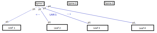
- Connect each Spine switch to each and every leaf switch exactly once. Beginners could use the following scheme:
    Spine1-port1 -> Leaf1-port1		Spine1-port2 -> Leaf2-port1 		Spine1-port3 -> Leaf3-port1
    Spine2-port1 -> Leaf1-port2		Spine2-port2 -> Leaf2-port2 		Spine2-port3 -> Leaf3-port2
    Spine3-port1 -> Leaf1-port3		Spine3-port2 -> Leaf2-port3 		Spine3-port3 -> Leaf3-port3
- Making the port number identify to which switch the cable is connected to.
The Flipped Network uses (# of spines) x (# of Leafs) cables and, as you can see, scales linearly with the respect to the number of client ports; in this case 3x4= 12 cables of a fully connected mesh network scales cubically, n*(n-1)/2 cables, with respect of the number of client ports. 7 switches in a full mesh requires 7*6/2=21 cables.
¶ B) Layer 2 and Layer 3
Here comes the trick: Make sure that the Layer 2 broadcast zone ends at the spine ports of the leafs. Make the port a routed port with an IP address using the command
  interface range 1/0/1 - 24
    no switchport
The leaf now becomes a router where every port has an IP-address, a task that suits a Multilayer switch very well.
¶ C) Fabric Ports
Consequently, every cable connected to a particular spine becomes a single LAN, a single broadcast-zone, which of course must have connected leaf ports in the same IP-network. In our example the blue(?) cables on spine 1 would be one LAN with the IP-addresses in 10.0.1.0/24, and
port 1 of leaf 1 could have the IP-address 10.0.1.1/24,
port 1 of leaf 2 could have the IP-address 10.0.1.2/24,
port 1 of leaf 3 could have the IP-address 10.0.1.3/24 and
port 1 of leaf 4 could have the IP-address 10.0.1.4/24.
All 4 in the same L3 network.
Consequently, in our example you could number
port 2 of leaf 1 could have the IP-address 10.0.2.1/24,
port 2 of leaf 2 could have the IP-address 10.0.2.2/24,
port 2 of leaf 3 could have the IP-address 10.0.2.3/24 and
port 2 of leaf 4 could have the IP-address 10.0.2.4/24.
All 4 in another L3 network. Etc etc.
Foreach { $portno towards spine }
  interface TenGigabit $portno
    ip address 10.0.$portno.$leafno 255.255.255.0
--DON'T DO THIS ---------- if you are using an old L2-switch, like c2950, you can still do this with the folloeing modification:
( a bit harder to understand since the port needs to be an access port of that VLAN, and that the VLAN only has local significance:
☆ no correlation with VLANS on other leafs, ☆ no trunks and ☆ still no configuration of the spines)interface TenGigabit $portno switchport mode access switchport access vlan $portno interface vlan $portno ip address 10.0.$portno.$leafno 255.255.255.0
¶ D) Client Ports
Until now we have only configured the internal networking of the Flipped Network, the fabric you may say.
Usually Client Ports are not a part of the underlay, rather the overlay, but who cares; let's test some stuff...  ping is fun!
The client ports where we put our servers are also routed ports with IP-addresses in the flipped network. The IP-address of these should hierarchy include Flipped Network (10), a leaf (10.0) the port number (10.0.4) and the default gateway of that LAN (10.0.4.1). Server admins tend to get confused if the way towards the network isn’t dot1 (.1).
This gives us the configuration:
foreach { $portno towards server }
  interface TenGigabit $portno
    ip address 10.$switchno.$portno.1 255.255.255.252
¶ E) Underlay Routing --- Connecting the LANs
Now we have a bunch of LANs that can communicate internally, and sometimes also to directly connected ones. To facilitate communication throughout the network routing is required on all leaf nodes. Dynamic routing is the preferred method because of its simplicity and stability through “keepalive” packets.
ip routing
  router ospf 1
  network 10.0.0.0 0.255.255.255 area 0
OVER-THE-TOP; no need to do this, but interesting to know...
Sometimes you need to tweak the load balancing scheme of CiscoExpressForwarding (CEF) with the command
ip cef load-sharing algorithm include-ports source destination
¶ F) Routing towards the Internet
If your network needs connectivity with some other network, it is paramount that you do not connect any extra cables to the spines! The correct way to connect stuff is via the server (client) ports on the leafs. Preferable one link on the first leaf and one link on the last for redundancy and good looking topology-maps.
Reachability for other networks and to the Internet is easiest facilitated by a default route propagated from the leafs that actually have an upstream connection. Assuming the “Internet port” is port24, and the internet-router has an IP-address ending in .2, the code would look the same on both internet-connected leafs:
 ip route 0.0.0.0 0.0.0.0 10.$thisleafno.24.2
 router ospf 1
   network 0.0.0.0 area 0      or better      default-information originate
Example pictures:
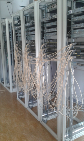 I-I-I-I-I-I-I-I-I-I-I
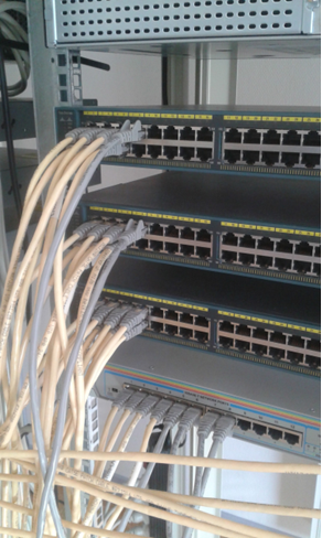
*An 8-leaf, 7-spine example *
¶ G) Testing the network for connectivity
-
Connect two PC’s to two different Leaf switches
-
Statically assign .2 addresses and the default gateway address of that port the PC is attached to.
-
Traceroute multiple times and see what path the packets take through the fabric
-
Try show ip route and verify that client networks have multiple lines (different next-hop; same target)
-
Test more stuff

¶ This is how a 2x2 Flipped Network looks like internally with EIGRP
This network consisted of Spine-1, Spine-2, Leaf-3 and Leaf-4.
Leaf-4#show ip route

Gateway of last resort is not set
      10.0.0.0/8 is variably subnetted, 10 subnets, 2 masks
C        10.1.1.0/24 is directly connected, FastEthernet0/1
L        10.1.1.4/32 is directly connected, FastEthernet0/1
C        10.2.2.0/24 is directly connected, FastEthernet0/2
L        10.2.2.4/32 is directly connected, FastEthernet0/2
D        10.3.10.0/24 [90/30720] via 10.2.2.3, 1d19h, FastEthernet0/2
                      [90/30720] via 10.1.1.3, 1d19h, FastEthernet0/1
D        10.3.11.0/24 [90/30720] via 10.2.2.3, 1d19h, FastEthernet0/2
                      [90/30720] via 10.1.1.3, 1d19h, FastEthernet0/1
C        10.4.12.0/24 is directly connected, FastEthernet0/12
L        10.4.12.4/32 is directly connected, FastEthernet0/12
C        10.4.13.0/24 is directly connected, FastEthernet0/13
L        10.4.13.4/32 is directly connected, FastEthernet0/13

Leaf-4#show ip cef 10.3.10.0 internal
10.3.10.0/24, epoch 3, RIB[I], refcount 6, per-destination sharing
  sources: RIB
  feature space:
   Broker: linked, distributed at 4th priority
  ifnums:
   FastEthernet0/1(469): 10.1.1.3
   FastEthernet0/2(470): 10.2.2.3
  path 0625780C, path list 053A00B0, share 1/1, type attached nexthop, for IPv4
  nexthop 10.1.1.3 FastEthernet0/1, adjacency IP adj out of FastEthernet0/1, addr 10.1.1.3 058EF420
  path 0625787C, path list 053A00B0, share 1/1, type attached nexthop, for IPv4
  nexthop 10.2.2.3 FastEthernet0/2, adjacency IP adj out of FastEthernet0/2, addr 10.2.2.3 058EF280
  output chain:
    loadinfo 0588EE68, per-session, 2 choices, flags 0003, 6 locks
    flags: Per-session, for-rx-IPv4
    16 hash buckets
      < 0 > IP adj out of FastEthernet0/1, addr 10.1.1.3 058EF420
      < 1 > IP adj out of FastEthernet0/2, addr 10.2.2.3 058EF280
      < 2 > IP adj out of FastEthernet0/1, addr 10.1.1.3 058EF420
      < 3 > IP adj out of FastEthernet0/2, addr 10.2.2.3 058EF280
      < 4 > IP adj out of FastEthernet0/1, addr 10.1.1.3 058EF420
      < 5 > IP adj out of FastEthernet0/2, addr 10.2.2.3 058EF280
      < 6 > IP adj out of FastEthernet0/1, addr 10.1.1.3 058EF420
      < 7 > IP adj out of FastEthernet0/2, addr 10.2.2.3 058EF280
      < 8 > IP adj out of FastEthernet0/1, addr 10.1.1.3 058EF420
      < 9 > IP adj out of FastEthernet0/2, addr 10.2.2.3 058EF280
      <10 > IP adj out of FastEthernet0/1, addr 10.1.1.3 058EF420
      <11 > IP adj out of FastEthernet0/2, addr 10.2.2.3 058EF280
      <12 > IP adj out of FastEthernet0/1, addr 10.1.1.3 058EF420
      <13 > IP adj out of FastEthernet0/2, addr 10.2.2.3 058EF280
      <14 > IP adj out of FastEthernet0/1, addr 10.1.1.3 058EF420
      <15 > IP adj out of FastEthernet0/2, addr 10.2.2.3 058EF280
    Subblocks:
     None
Leaf-4#
¶ H) Connect VLAN PortGroup to topology
TASK: Access PortGroup
On Leaf-1 issue the commands:
Leaf-1(config)# interface range gi 1/0/14 – 23
   Leaf-1(config-if)# switchport
   Leaf-1(config-if)# switchport mode access
   Leaf-1(config-if)# switchport access vlan 2
What more is required to restore connectivity between hosts (servers) on vlan2 and the fabric? Is it a SVI??
¶ I) True External Connectivity
TASK: External DHCP-server
Add a router to one Leaf switch (port 24) and give it an IP-address.
Over the top (optional): What commands are required to make it an DHCP server for all client ports on the leaves ? Do you remember the command ip helper from CCNA-3 ??
TASK: True Internet Connectivity
- Connect the Port24 router (from the above task) to CNAP-switch (Internet)
- Give the CNAP-port of the router an address using DHCP client. (
ip address dhcp) - Move the "default information originate" from the leaf to the router
- Create a NAT address translator on the router (not on leaf, not on spine)
access-list 1 permit 10.0.0.0 0.255.255.255//
ip nat inside source list 1 interface gi 1/0/X overload
ip nat insideip nat outside - Solve the routing for the PC clients with default information originate
Test Internet connectivity from the Client PC's by accessing this web-page.
¶ End of Lab
GLHF